Chapter 4. Cast Shadow
- J. Colannino
- Aug 2, 2017
- 7 min read
Last updated 23 December 2018.
In parallel projection (a.k.a., zero-point perspective, 0PP), parallel lines remain parallel in all directions, therefore, it is a simple matter to determine shadows via parallel projection: we merely place triangle ABC (or any similar triangle) at each corner with a view of the sun. For the cube shown, these would be the top corners of the cube (1, 2, 3, 4). By similar triangle, we mean any angle-preserving triangle of whatever size necessary to intersect the object feature and the ground plane. Figure 1, left shows a compound angle described by an azimuthal angle (a) and a polar angle (p).

Figure 1. Objects illuminated by light at compound angle a x p.
In the middle figure above, the sun strikes every corner that has a view of the sun at compound angle a, p . If the corner is above ground level (1, 2, 3, 4) and intercepts the sun's rays, a shadow will be formed. The boundary of the shadow will be mapped by the intersection of the light ray (blue lines) with the ground plane (1' 2' 3' 4') unless occluded by the object itself. For this reason, the shadow boundary at 1’ is forbidden because the cube itself blocks the light from the ground. From the above map, the shadow’s edge will begin from the leftmost corner, to 3’, 4’, 2’, and finally to the rightmost corner (red outline). A cast shadow will therefore exist everywhere between the shadow boundary and the cube. The figure at right shows the same technique applied to a solid hexahedron suspended above the ground. The light ray 1a-1a’ is occluded by the object (as is the light ray 4b-4b’). However, the projection from the bottom corner 1b is clear to proceed to 1b’. In this way, the shadow outline 3b’-3a’-4’-2a’-2b’-1b’-3b’-3a’ is drawn.

Figure 2. The power of shade and shadow.
Figure 2 shows how shade and shadow can be a key consideration in the perception of depth. Shade is distinguished from shadow in that shade is attached to the object while shadow is cast by the object onto a foreign surface. To heighten the illusion, I've shaded the sides of the object that cannot see the sun (edges facing viewer). In Figure 2, both objects are identical in size and vertical position. Yet the left figure seems to recede into the background while the right figure appears to come forward. This is because the shadow placement on the right figure demands that the object be elevated above the ground plane; however, the cast shadow on the left demands that the object be sitting on the ground. In real life, this can only be so if the right figure is closer to the viewing plane than the object at left. As noted in the chapter on perspective and contrary to popular opinion, 0PP objects have a depth dimension, so your perceptual apparatus makes the necessary adjustment. The result is a perception of the object at right appearing higher and closer (and a bit smaller) despite the fact that both are identical in size and vertical position.
You may call this an optical illusion if you choose, but it is your perceptual apparatus making sense of an image consonant with the object at right being closer and more elevated and casting a shadow in 3D. Of course, all pictures ARE an illusion because one is viewing a flat piece of paper on which the artist has constructed figures mimicking the 2D retinal image of a desired 3D scene. More wonderful than the illusion is the design of such a remarkable visual apparatus that allows effective navigation in a three-dimensional world. The retina is about 10% of the head of a pin in area. Yet it captures two-dimensional images, post processes and highly compresses them before sending the data along a highway known as the optic nerve. From this, the visual apparatus interprets objects in a three-dimensional world. This is an absolute marvel of information processing beyond the ken of modern science.
[“The hearing ear and the seeing eye, YHWH has made them both.” (Pr 20.12) Indeed, the overlooked miracle in Jesus healing the man born blind is not merely that the man's sight was restored, but that he was able to interpret a three-dimensional world without the years of training required in infancy to wire and calibrate the visual apparatus.]
Projection of shadow on oblique surfaces
Even if the shadow surface is oblique to the ground plane, the principle for casting shadows remains the same: we find where the sun's rays intersect the surface to establish the boundaries for the shadow.

Figure 3. Cast shadow on an inclined plane.
Figure 3a shows how we map a light ray (AB) to the surface of an inclined plane. As before, we shall use triangle ABC (or any similar triangle) to indicate the direction of the sun’s rays. We construct another triangle (DEF) such that DE and BC share an edge. This gives line EF on the ramp along the direction the sun’s rays. BC and DE always rest on the ground plane and the intersection of AB x EF indicates where on the surface of the ramp the shadow boundary will fall (black dot). Triangle ABC (or similar) is then moved to each boundary of the object with a view of the sun and Triangle DEF is moved such that E rides along the left edge of the ramp (blue line). For construction purposes, we may have to extend this edge (dotted blue arrows). In Figure 3b we have superimposed the object of Figure 2. (For comparison only, the shadow on the ground plane is shown, although it cannot exist since the ramp blocks the sun’s view of the ground plane.) Additionally, we show the construction of one corner of the shadow on the surface of the ramp (black dot). Figure 3c shows the result of the completed procedure (dark shadow). Figure 4 shows the finished result with all the construction construction lines and reference shadow removed.

Figure 4. Cast shadow on an inclined plane.

Forward Cast Shadow in 1PP
In 1PP, we have one vanishing point and recession of depth in one dimension (see Perspective for details). A 1PP cube is drawn in the usual way projecting toward a single VP (gray lines). In this case, the length and shape of the cast shadow are determined by the placement of the sun over the horizon. We shall call this the solar point (ZP), see figure at right. Let us focus on one particular boundary of the shadow (X) made by the top left corner of the cube. The plane of light that we are concerned with is the one which hosts the triangle ZP-X-ZVP. ZVP is the solar vanishing point from which all ground lines (GLs) emanate, and it is always a direct vertical projection from the sun to the horizon. This is the plane of light interrupted by the left edge of the cube and it contains the sun's sight line (ZL) from the corner of the cube to the sun and the respective ground line. As usual, the process is repeated for each boundary of the object having a view of the sun (the top rear corner is occluded by the object itself and therefore cannot cast any shadow). This results in the shadow boundary shown in the figure. Note that where the shadow boundary parallels the object edge boundary, it also projects to the VP (far right vanishing line).
Note also that the ground lines must run along the ground plane (obviously). Therefore, if the object is lifted from the ground, the ground line must go through the vertical projection of the object to the ground (dotted green lines under the cube) not to the object itself which no longer contacts the ground.

Rearward Cast Shadow.
When the shadow is cast rearward, the sun must be behind the viewing plane. In that case, the ZP cannot be shown. However, we can use an anti-solar point (AZP). This is the projection of the sun from behind the viewer through the earth and 93 million miles beyond the night sky. Conveniently for the artist, this is just a few inches away.
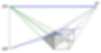
Figure 5. Rearward cast shadow.
In Figure 5, the sight lines (blue arrows) come from behind the viewing plane and terminate at the respective ground lines (green). I have dotted the lines below the ground plane where they continue until reaching the AZP. As before, the shadow boundary is defined where the ZLs intersect the GLs. I have rendered the cube translucent so that the shadow boundary may be better apprehended. Remember, the shadow is being cast by the interrupted light plane hosting the ZL, GL, and object boundary. Planes of this sort can be difficult to visualize, so for reference, I have drawn in a portion of the light plane intersecting the left edge of the cube (heavy blue lines).
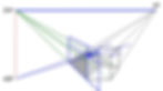
At right is the opaque cube with rearward cast shadow.

Shadows in 2PP
Shadows in 2PP are no different than 1PP. If the same rules are followed then proper shadow will result.


Shadows in 3PP
3PP shadows follow the same rules. The only wrinkle is that the vertical lines including ZP-ZVP must vanish to VP3 (see right figure). Below is a close up of the object with the construction lines removed.

Shadows for Still Lifes
Shadows in still life pictures introduce two minor complications. First, lighting is often interior rather than solar and in such a case is often diffuse, forming less defined shadow edges (although this may also occur with solar lighting if the day is overcast or other light scattering media such as snow, smoke, or fog are present). Second, still life objects are usually more complicated in shape than buildings and structures. However, and as we have already seen in Chapter 3, more complicated shapes can always be surrounded by simpler shapes enveloping key points and these key points may then be mapped to define boundaries — in this case and as before — to key points on the surface hosting the cast shadow (X). To indicate a change from exterior to interior lighting, the solar point (ZP) is now replaced by the light point (LP) and the solar vanishing point (ZVP) is replaced by the light vanishing point (LVP). The projection of a light ray from the source to a point normal to the surface hosting the cast shadow (i.e., impacting the surface at 90°) defines the LVP. Finding the portion of the light plane formed by the triangle LP-LVP-X provides all we need to know to map a point from the object on to the shadow plane (Figure 6). In lieu of solar lines (ZLs) we have light lines (LLs). Since the location of the light source is known, it is a simple matter to project lines from it without the need to worry about whether the shadow is forward or rearward projecting.

Figure 6. Cast shadow in a still life
Further Reading


